Electric Thermal Oil Heater 80 KW

Electric Thermal Oil Heater 80 KW MFG PT Indira Mitra Boiler Specialist Pabrikasi a Steam Boiler

General Description:

The Electricity Heating Thermal Oil Heater is an efficient low-pressure high-temperature heating equipment, which uses electricity as a heat source and heat transfer oil as a heat carrier, passing thermal energy to the heat users through the forced circulation of the hot oil pump, and returning to the Heater for reheating and recirculation.

  1. Product features and uses:

 2.1 Product features:

(1)The Thermal Oil Heater can provide a higher process temperature (≤300 degrees) under lower pressure to replace the high and medium pressure boiler to heat. Compared with the steam boiler, the electric heating boiler needs lower pressure, which will greatly increase security, improve the working environment, reduce labor intensity and the one-time investment, and have no pollution.

It has a sensitive electronic automatic temperature control system that provides reliable high precision, uniform heat transfer, and good process performance.

(2)The Thermal Oil Heater has a compact structure, small size, lightweight, small footprint, and simple installation. It is the new generation of heating equipment in the modern light industry, chemical, and other industries.

(3) Its temperature regulation is accurate and reliable, equipped with temperature, liquid level, and a security alarm device.

(4)It has high thermal efficiency (≥90%).
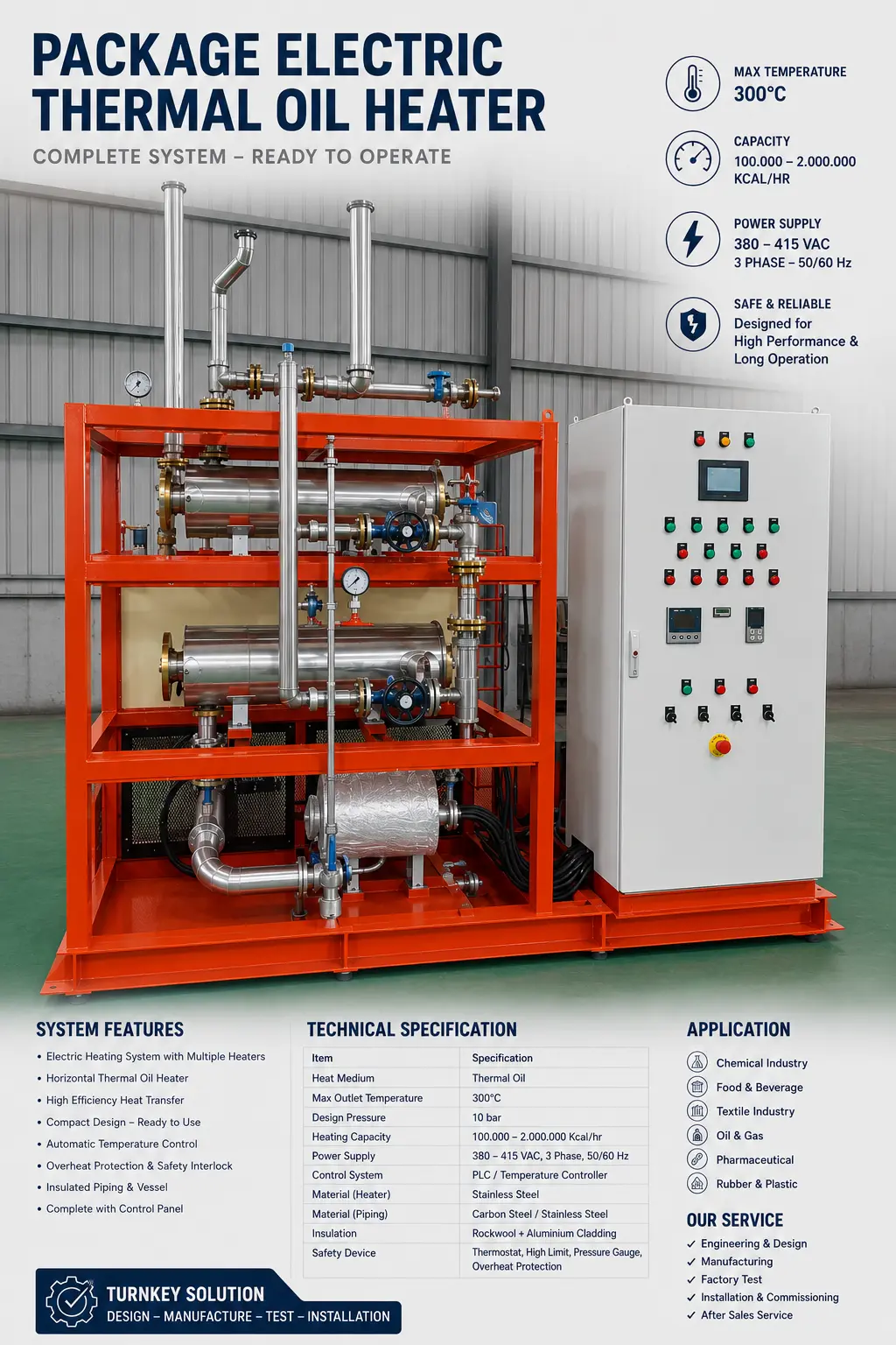
BEJO Electric Thermal Oil Heater manufactured by PT Indira Mitra Boiler
bejo electric thermal oil heater by pt indira mitra boiler

 2.2 Uses:

This series of Thermal Oil Heater can be used in the following industries: (1)Petroleum and chemical industry: polymerization, condensation, distillation, dehydrogenation, and forced insulation.

(2)Oil industry: fatty acid distillation, oil decomposition, concentration, esterification, vacuum deodorization.

 (3)Timber industry: multi-plywood, fiberboard, hot press molding, wood drying.

(4)Building materials industry: gypsum board drying, asphalt heating.

(5)Textile industry: heat setting, drying, hot-melt dyeing.

(6) Food industry: baking bread, biscuits.

(7)Plastics and rubber industry: calendering, extrusion.

(8)The Thermal Oil Heater is widely used in light and pharmaceutical industries production.

  1. Working principles:

IDM series Thermal Oil Heater uses the heat transfer oil as a heat carrier. The heat transfer oil in the Heater body is heated to the desired temperature by the electric heating elements, then is transported to the relative devices by the hot oil pump to pass thermal energy. At last, the oil is transported back to reheat to make a continuous heating process.

  1. Basic structure:

The whole complete set of thermal oil Heater consists of the heating system, the circulation system, the electronic control system, and the expansion system.

4.1The heating system:

the main component is the electric heating oil Heater, it consists of the heating pipes, inlet and outlet oil pipes, frame, diversion devices, and protection cover.

4.2 The circulation system:

the filter, high-temperature oil pump, oil Heaterpipe, valves, and heat-demanding equipment constitute a closed loop.

4.3The expansion system:

It mainly consists of the housing body, expansion pipe, overflow pipe, exhaust pipe, sewage outlet pipe, plate level gauge, and float level controller.

Its role is to accept the expansion oil, compensate the circulatory system, supercharge, exhaust, alarm oil level, and spill oil. The volume of the expansion slot can be configured according to the user’s requirements.

4.4 The electronic control system:

the electrical control cabinet is the main operation control part of the Thermal Oil Heater, and it plays a very important part in starting the pump, heating(stopping) temperature, controlling temperature, displaying temperature, and liquid level alarm.

#oil Heater_pipe#heating_system #circulation_system

TABEL OIL HEATER

Type

Specification

IDM

0.036

IDM

0.048

IDM

0.06

IDM

0.072

IDM

0.09

IDM

0.12

IDM

0.18

IDM

0.24

IDM

0.30

IDM

0.36

Heating Power  (kw)

36

48

60

72

90

120

180

240

300

360

 (×10kcal/h)

3

4

5

6

7.5

10

15

20

25

30

Highest  Operation

Temperature

300

Temperature Accuracy

±5

Thermal Efficiency

>90%

Design  Pressure (Mpa)

0.7

Oil   Cycle   (m³ / h)

10

12.5

18

18

18

18

30

45

50

50

Motor  Power  (Kw)

2.2

3

5.5

5.5

5.5

5.5

7.5

11

15

15

Connecting

Pipe (DN)

  (mm)

Output

32

50

50

50

50

50

50

65

65

80

Circuit

32

50

50

50

50

50

65

80

80

80

Dimensions(mm)

1785×

560×

1420

2000×

560×

1420

2000×

550×

1440

2000×

650×

1510

2650×

650×

1510

2000×

800

×1440

2000×

800×

1760

2000×

900×

1910

2000×

940×

2145

2000×

940×

2328

Weight(Kg)

375

460

495

580

620

662

840

1018

1350

1705


Electric Thermal Oil Heater 80 kW Manufactured by PT Indira Mitra Boiler

PT Indira Mitra Boiler specializes in the design, fabrication, installation, and commissioning of industrial heating systems, including steam boilers, Thermal Oil Heaters, hot-water boilers, electric boilers, and burner systems.

The 80 kW Electric Thermal Oil Heater is designed for industrial processes requiring stable and accurate temperature control without combustion, fuel storage, exhaust gas, or a chimney.

Electric Thermal Oil Heater Case Study

A manufacturing company required an indirect heating system for a production process. The existing heating method produced an unstable temperature and required frequent operator supervision.

The customer requested a system with the following characteristics:

  • Clean operation without combustion gases.
  • Accurate process-temperature control.
  • Automatic operation.
  • Compact installation.
  • Low noise.
  • No chimney or burner.
  • Easy integration with existing production equipment.
  • Complete electrical and thermal safety protection.

Based on these requirements, PT Indira Mitra Boiler proposed an 80 kW Electric Thermal Oil Heater.

Proposed Technical Specification

DescriptionSpecification
EquipmentElectric Thermal Oil Heater
ManufacturerPT Indira Mitra Boiler
Heating capacity80 kW
Equivalent thermal capacityApproximately 68,800 kcal/h
Heating methodElectric heating elements
Heat-transfer mediumThermal oil
Operating temperatureUp to approximately 250–280°C
Control systemAutomatic temperature control
Electrical supply380–400 V, three-phase, 50 Hz
Operating pressureCirculation-pump pressure
InstallationIndoor or protected outdoor area
EmissionsNo on-site combustion emissions
ChimneyNot required

The final operating temperature must be adjusted to the thermal-oil specification, heater design, pump selection, and process requirements.

Capacity Conversion

The thermal capacity is converted using:

Therefore:

The heater provides approximately 68,800 kcal/h of thermal energy at full electrical load.

System Components

The proposed Electric Thermal Oil Heater consists of the following main components:

  • Heater vessel or heating chamber.
  • Industrial electric heating elements.
  • High-temperature circulation pump.
  • Expansion tank.
  • Thermal-oil piping.
  • Isolation and drain valves.
  • Temperature sensors.
  • Pressure gauge.
  • Flow-protection device.
  • Electrical control panel.
  • Thermal insulation and metal cladding.
  • Automatic safety interlocks.

Electric Heating Elements

Industrial electric heating elements convert electrical energy directly into heat. The elements are installed inside the heater chamber, where heat is transferred to the circulating thermal oil.

To improve temperature control, the total heating capacity can be divided into several stages. For example, an 80 kW heater may use four heating stages of 20 kW each.

This arrangement provides several operational benefits:

  • More stable temperature control.
  • Reduced switching frequency.
  • Lower temperature overshoot.
  • Flexible response to changing process loads.
  • Easier maintenance of individual heating stages.
  • Reduced electrical loading during start-up.

Thyristor or SCR control can also be used when the process requires finer and continuously variable power regulation.

Thermal-Oil Circulation System

A high-temperature circulation pump transfers heated thermal oil from the heater to the process equipment. After releasing its heat through a coil, jacket, or heat exchanger, the oil returns to the heater.

The circulation pump must be selected based on:

  • Required thermal-oil flow.
  • Total piping length.
  • Heater pressure drop.
  • Process-equipment pressure drop.
  • Number of valves and fittings.
  • Thermal-oil viscosity.
  • Operating temperature.
  • Installation elevation.

Sufficient circulation must be maintained whenever the heating elements are energized. Low flow can cause excessive surface temperature, thermal-oil degradation, and damage to the heating elements.

Electrical Power Requirement

At full load, the heating elements consume approximately 80 kWh for every hour of continuous operation.

The circulation pump and control system create an additional electrical load. For example, if the pump motor and auxiliary components consume 5 kW, the estimated total connected load becomes:

The required electrical current can be estimated using:

Using an 80 kW heater load, a 400 V supply, and a power factor of approximately 1.0 for resistive elements:

The electrical panel, cable, circuit breaker, contactor, and busbar must therefore be selected with an appropriate engineering and safety margin. The pump and auxiliary loads must be calculated separately.

Automatic Control Panel

The control panel acts as the central operating and safety system. It can be equipped with:

  • Main circuit breaker.
  • Heater contactors or thyristor controller.
  • Circulation-pump motor starter.
  • Overload protection.
  • Digital temperature controller.
  • Inlet and outlet temperature indicators.
  • High-temperature limiter.
  • Phase-failure relay.
  • Phase-sequence protection.
  • Voltmeter and ammeter.
  • Automatic and manual selector switches.
  • Emergency-stop button.
  • Pilot lamps.
  • Audible alarm.
  • PLC and HMI as optional features.

The control panel can also provide signals to the customer’s central control system.

Safety Interlock System

The heating elements must not operate until the circulation pump has started and adequate thermal-oil flow has been confirmed.

Recommended safety interlocks include:

  • Low thermal-oil flow protection.
  • High outlet-temperature shutdown.
  • Independent overtemperature limiter.
  • Circulation-pump overload protection.
  • Low expansion-tank level alarm.
  • Phase-failure and phase-reversal protection.
  • Heater-element short-circuit protection.
  • Emergency shutdown.
  • Abnormal pressure alarm.
  • Sensor-failure protection.

If the circulation pump stops during operation, the system must disconnect the heating elements immediately.

Expansion Tank Function

The expansion tank accommodates the increase in thermal-oil volume as the temperature rises. It also helps remove trapped air and maintain stable suction conditions for the circulation pump.

The tank must provide sufficient space for:

  • Thermal expansion.
  • Operating reserve.
  • Air separation.
  • Safe filling and draining.
  • Thermal-oil level monitoring.

The expansion tank should be positioned and designed to keep the oil surface temperature relatively low, thereby reducing oxidation.

Estimated Heating-Time Example

The following example assumes that 1,000 kg of thermal oil must be heated from 30°C to 200°C.

Assumptions:

  • Thermal-oil mass: 1,000 kg.
  • Average specific heat: 0.50 kcal/kg°C.
  • Temperature increase: 170°C.
  • Heater capacity: 68,800 kcal/h.
  • Heat-loss allowance: 15%.

The basic heat requirement is:

Including 15% heat loss:

The estimated heating time is:

The theoretical heat-up time is approximately 1 hour and 25 minutes. Actual heating time may be longer because the heater must also warm the piping, process equipment, insulation, and product.

Commissioning Procedure

The commissioning process includes:

  1. Inspecting the heater, piping, valves, pump, and electrical connections.
  2. Filling the installation with the recommended thermal oil.
  3. Venting trapped air from the system.
  4. Starting the circulation pump without energizing the heaters.
  5. Checking pump rotation, flow, pressure, and leakage.
  6. Testing all alarms and safety interlocks.
  7. Energizing the heating elements gradually.
  8. Increasing the thermal-oil temperature in controlled stages.
  9. Removing residual moisture from the system.
  10. Confirming the temperature-controller setting.
  11. Recording current, voltage, temperature, pressure, and flow.
  12. Providing operational training to the customer’s personnel.

The initial temperature must be increased gradually, particularly if the piping or thermal oil contains residual moisture.

Results and Operational Benefits

After installation and commissioning, the 80 kW Electric Thermal Oil Heater provides the following benefits:

  • Stable process temperature.
  • Accurate automatic control.
  • Clean operation without fuel combustion.
  • No chimney requirement.
  • No fuel tank, gas train, or fuel pump.
  • Low operating noise.
  • Reduced routine burner maintenance.
  • Easy integration with production equipment.
  • High electrical-to-heat conversion efficiency at the heater.
  • Improved working conditions around the heating system.

Electric Heater Versus Fuel-Fired Heater

ParameterElectric Thermal Oil HeaterFuel-Fired Thermal Oil Heater
Energy sourceElectricityGas, diesel, or other fuel
BurnerNot requiredRequired
ChimneyNot requiredRequired
On-site combustion emissionsNonePresent
Temperature controlHighly precisePrecise with modulation
Installation spaceRelatively compactGenerally larger
Routine maintenanceRelatively lowBurner maintenance required
Initial installationSimpleRequires fuel and flue systems
Operating costDepends on electricity tariffDepends on fuel price
Suitable capacitySmall to medium dutiesMedium to very large duties

Conclusion

The 80 kW Electric Thermal Oil Heater manufactured by PT Indira Mitra Boiler is suitable for industrial processes requiring clean, reliable, and accurately controlled indirect heating.

Its compact construction, automatic control system, staged electrical heating,.

Its compact construction, automatic circulation-pump interlock, and comprehensive safety devices make it suitable for reactors, mixing tanks, dryers, hot presses, food-processing equipment, chemical processes, and other industrial applications.

PT Indira Mitra Boiler provides engineering, fabrication, installation, commissioning, operator training, maintenance, and after-sales support for Electric Thermal Oil Heaters and industrial boiler systems.

PT Indira Mitra Boiler
Office: (021) 352 95874
WhatsApp: +62 813-8866-6204 (Ratman Bejo)
www.indiramitraboiler.co.id
www.burner.co.id
info@indira.co.id
idmratman@gmail.com
Workshop: Tangerang – Indonesia
https://www.youtube.com/@Bejoburnerindonesia
Scroll to Top